RoadVista Laserlux Retroreflectometer for Measuring Pavement Markings
Coefficient of Retroreflected Luminance (RL ) is the most commonly used measurement of retroreflectance in highway marking. RL is the ratio of the luminance (L) of a surface to the normal illuminance (E) on the surface. In the laboratory this definition works well with testing procedures.
This excerpt is taken from the RoadVista Guide to Retroreflectivity, for additional information download the free RoadVista Retroreflectivity Guidebook
In the applied world of roadway marker measurements, life is not so simple. In this situation RL translates into measuring the luminance of the marking against the normal illuminance of the incident light on the marking. In addition, the luminance would be the luminous flux of a light ray from the marking to the driver, per unit of projected area of the marking in your direction, per unit of solid angle. Also, since luminous intensity is just luminous flux per unit solid angle, the luminance is simply the luminous intensity of the light returned by the marking per unit area.
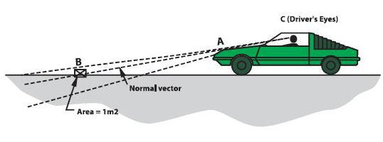
The normal illuminance (E) is the illuminance of a car's headlights on the marking, measured on a plane perpendicular to the direction of the headlight beams. Figure 7 will help you visualize these quantities. If the car shown is taken as a snapshot in time, then the observation and illumination angles are fixed. The headlights direct light of a specific intensity along the illumination axis. Since the quantities defined in the standards are directional, a single point must be identified on the marking where RL will be examined. This will be point B in the above figure. Having established this, a precise definition of the illumination axis is possible, directed along line AB.

By the time the light reaches point B, it has spread out through space and has a certain illuminance associated with it. If a plane is placed at point B with an area of one square meter and a normal vector in the same direction as line A, then the value of illuminance at B will equal the amount of light that would fall on this plane if the plane was illuminated in Figure 7 - Retroreflected light is returned in a cone in the direction of the light entirely by the same intensity of light as that directed at point B. The light will be reflected back in a cone shape around the direction of the headlight. It will have a specific luminous intensity in the observation direction along line BC.
Using the two values just mentioned, a value for coefficient of luminous intensity can be calculated. To calculate luminance and derive a value for RL, the luminous intensity per unit area must be found. The problem is that the luminous intensity per unit area must be determined to provide an appropriate area to use as a divisor. Up to this point, all the quantities have been directional, dealing with infinitesimal areas. The challenge is to accurately illuminate the sample at the proper angle, 88.76 degrees, and collect the light at the proper angle, 1.05 degrees, from the illumination axis. These angles simulate the illumination of the pavement marker by a car with headlights 0.65 meters above the pavement and 30 meters in front of the car and the driver's eye 1.2 meters above the pavement. By precisely setting this measurement geometry, you minimize the largest error-contributing factor, since the projected measurement area changes a large amount for a small change in the 88.76-degree illumination angle.

In practice, retroreflective or other materials are measured in a laboratory using a photometric range system.These material samples are used as transfer standards. A precision photometric range system consists of a projection light source, a photoreceptor, a method of setting the distance between these two components with precision and repeatability, and a retroreflective material sample holder with precise and repeatable angular setting mounted at least 10 meters from the light source and the photoreceptor. The projection light source is a precision instrument in itself, providing a less than 3% non-uniform illumination area with a tungsten halogen lamp operated at the correct 2855.6 degrees Kelvin color temperature stable over hundreds of hours of operation.
The
photoreceptor detector matches the human eye sensitivity at different colors throughout the visible region of the spectrum. Measurements of both the illumination at the retroreflection sample position and the retroreflected light from the sample are measured by the photoreceptor.The ratio of these two readings, including the projected area of the sample, is a direct determination of the coefficient of retroreflection. These laboratory-measured samples can then be used in the field as calibration standards to accurately set the intensity scale of the portable measurement instruments.
The decision on sample area in portable instruments differs from one manufacture to another, thus care must be taken when there is non-uniformity of the retroreflection of sample on the road. A typical example of this is with pavement stripes. It is not unusual to obtain a stripe where the center of a 4-inch wide retroreflected stripe will have a 2-inch wide stripe down the middle that has a coefficient of retroreflection value much greater than 1-inch to either side. If you used an instrument that only measured a 2-inch wide section of a stripe and compared it to an instrument that measured a 3-inch wide section of a stripe you would get a reading much lower with the 3-inch wide sample, which would agree much more closely with the true value and what the eye would see since the eye sees the whole 4-inch wide stripe.
The retroreflectometer instrument that measures only a 2-inch wide stripe would give a higher and thus faulty retroreflection value based on one measurement. The two instruments would agree more closely if 3 side-by-side measurements covering the full width of the stripe were made and averaged with the 2-inch wide instrument and then compared with the 2 measurements made and averaged with the 3-inch wide instrument. Typically, data from most modern instruments is reproducible if not accurate.
The unit used in roadway measurements is millicandelas per lux per square meter (mcd/lx/m²). This is equal to 0.001 of the basic unit, which was given before as candelas per lux per square meter (cd/lx/m²). When equipping a retroreflectance program, it is important to use a reliable and well-established instrument vendor that can support instrument calibration with a precise and repeatable laboratory measurement capability.
For additional information on retroreflectivity and highway safety download the RoadVista Retroreflectivity Guidebook
Other Posts on Retroreflection and Retroreflectivity